ENIGMA Chapter 4 – How Does the Machine Work? (Part 1)
Elements of the Enigma Machine
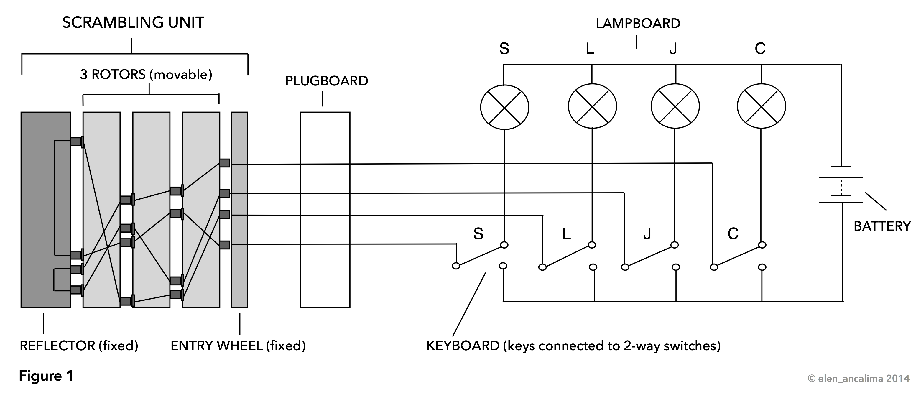
A simplified circuit diagram of an Enigma machine (Figure 1) with 4 of the 26 keys and indicator lamps shows the principle of how the various elements are connected to each other. If no key is pressed, there is no closed circuit, electricity cannot flow, and the lamps remain dark. Before going into more detail it might be helpful to familiarize oneself with the different parts of the Enigma machine.
(For those who want to delve deeper, the websites of the Crypto Museum, Dirk Rijmenants and Tony Sale are great online resources.)
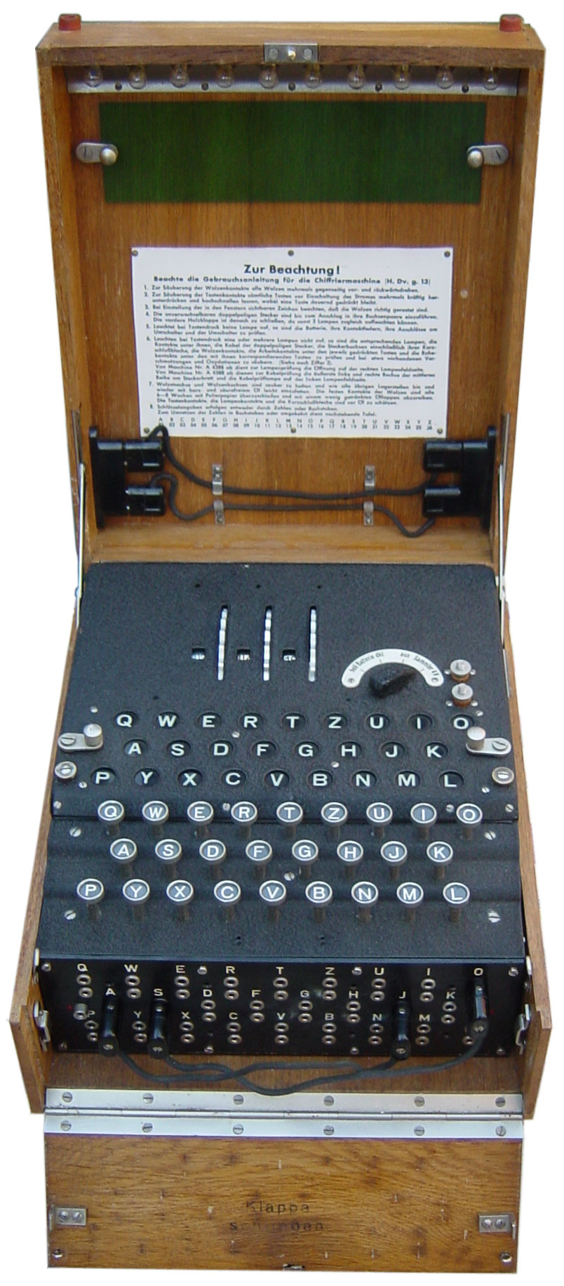 Keyboard: The keyboard (German Tastatur) has 26 letter keys arranged in the following order:
Q – W – E – R – T – Z – U – I – O
– A – S – D – F – G – H – J – K –
P – Y – X – C – V – B – N – M – L
Each key is connected to a 2-way switch. Pressing a key first causes one or more rotors to turn one step and then the switch closes a circuit. This allows electricity to flow from the battery through the plugboard and scrambling unit to one lamp on the lampboard. The exact electrical path is determined by the rotors, the reflector and (in military models) the plugboard settings.
Lampboard: The lampboard (German Lampenfeld) behind the keyboard has 26 round windows with letters, positioned over 26 small lamps. One of them lights up when a key is pressed, indicating the replacement for the plaintext letter typed on the keyboard.
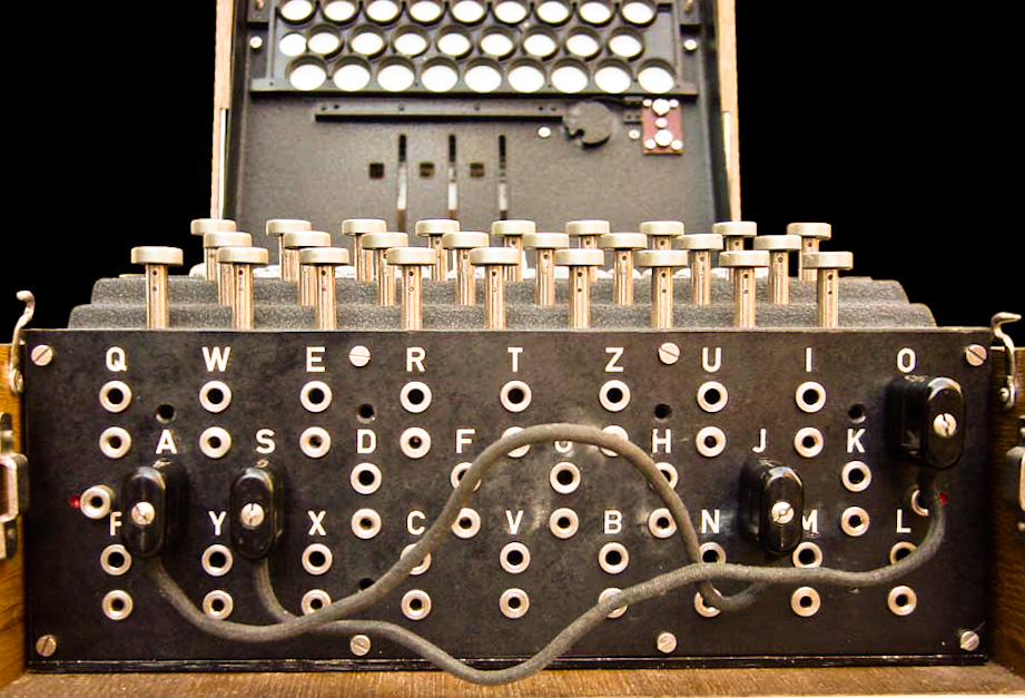
Plugboard: The plugboard (German Steckerbrett) is at the very front of the Enigma machine and was added to the military models in the late 1920s, making it more secure than the commercial version (see further Chapter 2). Letters are swapped by connecting their plugboard sockets with a cable, thereby diverting the flow of electricity before it enters the scrambling unit. If the two letters J and S are connected, for example, and the key for J is pressed, then current enters the scrambling unit at the S position on the entry wheel.
Before and during World War II, information on what letters were to be connected and thereby swapped on a specific day was set down in codebooks.
Entry wheel (stator): The fixed entry wheel (German Eintrittswalze) is the first part of the scrambling unit. Wires leading from all 26 keys are attached to it in alphabetical order (in military models). This is where electricity enters and exits the scrambling unit.
 Wheels (rotors): The wheels, also called rotors (German Walze), are the most important part of the Engima machine. Three different rotors (or four in the German Navy model) with different internal cross-wiring are mounted side by side on a spindle and placed between the entry wheel on the right and the reflector on the left. These three rotors are chosen according to the codebook information for that specific day from five (later eight) different possibilities: Rotors I, II, III, IV and V. Once placed into the machine, every rotor can be individually turned to the required setting.
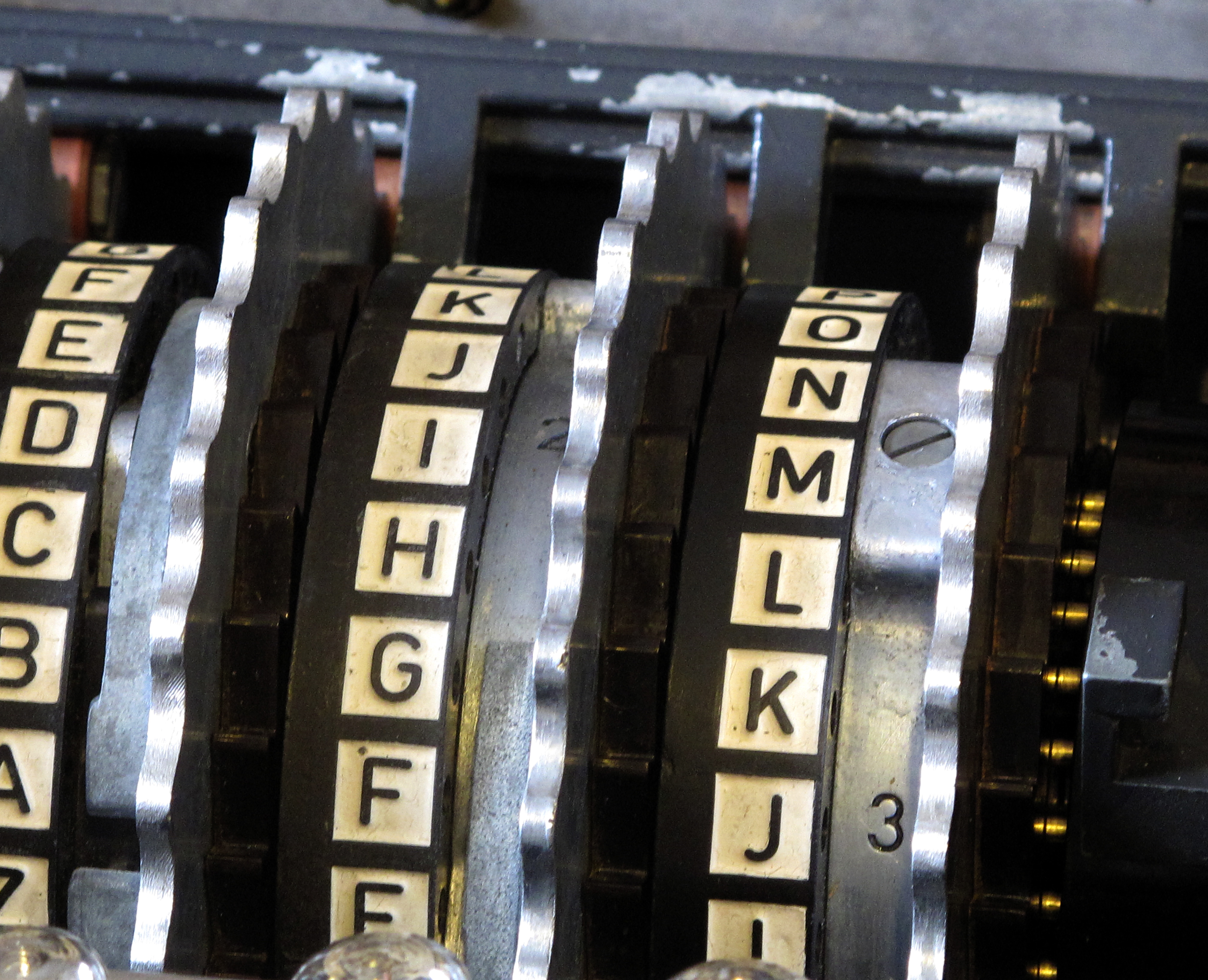
The three rotors turn at different speeds. The “fast” rotor on the right moves one step every time a key is pressed. Once every 26 turns, a notch on the wheel causes the rotor in the middle to turn as well. Since every rotor has a notch (each in a different position), the middle wheel can at one point also cause the leftmost “slow” rotor to step one position.
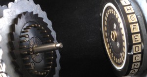
Every rotor has 26 spring-loaded pins on the right side and 26 flat contacts on the left, connected to each other through complex internal cross-wiring. These pins and contacts represent the alphabet, as marked by letters on the outer rim of the rotor (called the ring), with one letter visible to the operator through small window.
 Every pin on the right is connected with a wire to a flat contact on the left. The arrangement of these cross-wirings are different for every rotor. Rotor I for example connects the pin A to the contact E, while rotor III connects A with B.
Figure 2 shows the internal wiring of the three rotors I, II and III. (The colours are a visual help only and have no special meaning.) If electrical current enters the scrambling unit at A you can follow its path from right to left through the three rotors to the reflector, where it enters at Z and exits at T. From there electricity flows back through the three rotors from left to right on a different path, exiting at U. If any one of the rotors is moved by just one position, the entire constellation of wires changes. (Click image to magnify.)
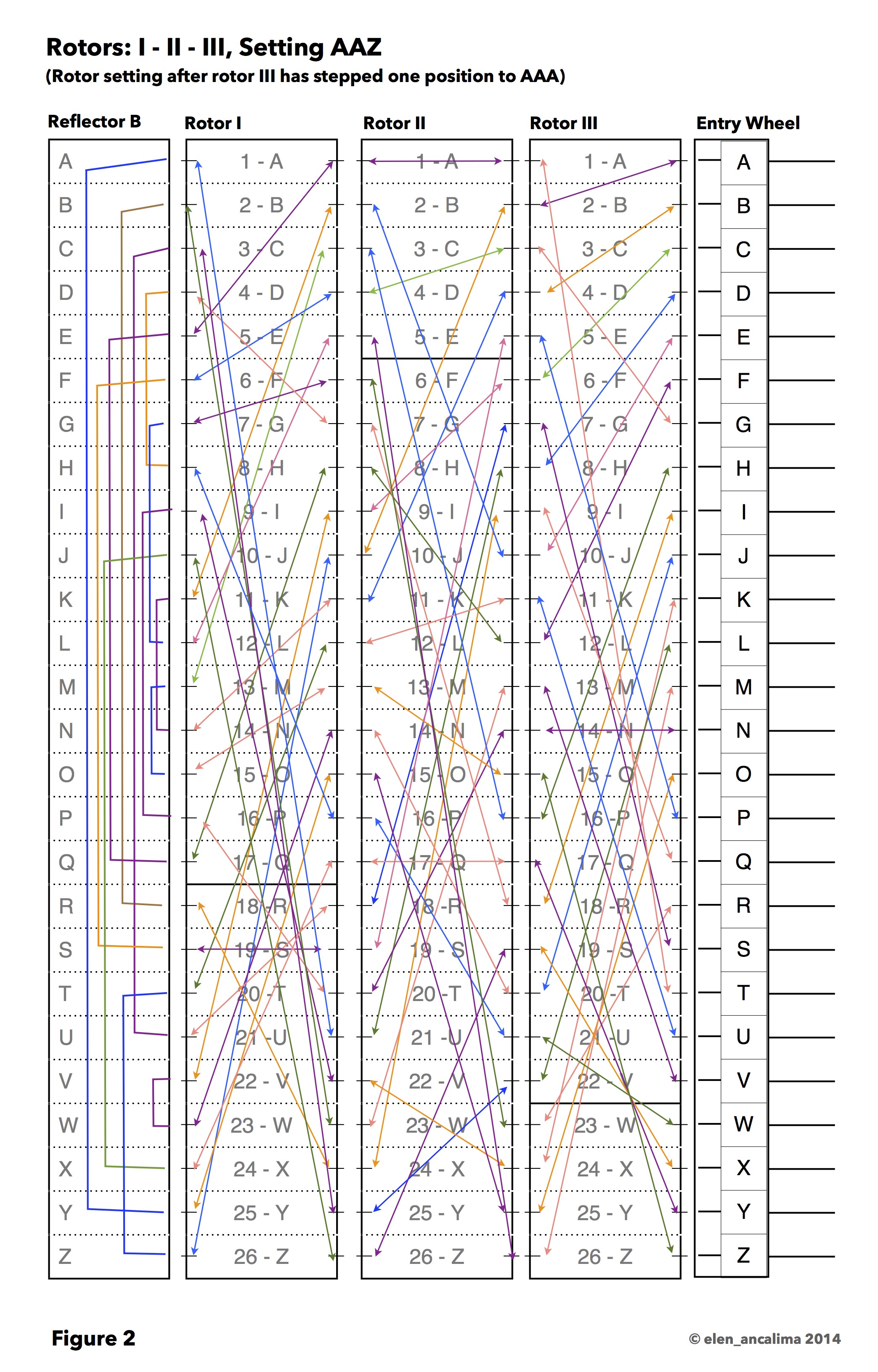
Reflector: A unique feature of the Enigma machine is the aforementioned fixed reflector (German Umkehrwalze). Its 26 pins on the right side are connected to each other through 13 internal wires, creating 13 linked letter pairs (as can be seen in Figure 2). Electricity flows from the leftmost rotor into the reflector, through one of the wires to exit at another pin.
The nature of the reflector means that encoding and decoding are mirror processes. At the same setting, A is encoded as U and U is encoded as A (see further Chapter 3). An unfortunate consequence of the reflector is the fact that no letter can ever be encoded as itself, which was helpful to codebreakers.
During World War II, the German Army and Air Force model used two different reflectors (B and C).
—
Continued in Chapter 4 Part 2
Previous posts:
Chapter 1 – Historical Background
Chapter 2 – The Invention of the Engima Machine
Chapter 3 – The Substitution Cipher
Chapter 4 – How Does the Machine Work? Part 1 and Part 2
FURTHER READING:
Books:
COPELAND, B. Jack. Turing. Pioneer of the Information Age. Oxford, 2012
SINGH, Simon. The Code Book. The Secret History of Codes and Code-Breaking. London, 1999
WELCHMAN, Gordon. The Hut Six Story. Breaking the Enigma Codes. Oxford, 1997
Websites:
Crypto Museum: Enigma (Retrieved April 2014)
RIJMENANTS, Dirk. Cipher Machines and Cryptology. Enigma Menu (Retrieved April 2014)
SALE, Tony. The components of the Enigma machine and Technical Specification of the Enigma (Retrieved April 2014)
Images:
http://enigmamuseum.com/u_060.jpg
http://en.wikipedia.org/wiki/File:Enigma-plugboard.jpg
http://en.wikipedia.org/wiki/File:Enigma_rotors_with_alphabet_rings.jpg
http://en.wikipedia.org/wiki/File:Enigma_rotors_and_spindle_showing_contacts_rachet_and_notch.jpg
http://www.cryptomuseum.com/crypto/enigma/img/exploded.gif
Figure 1 and Figure 2 © elen_ancalima
Write a comment
You need to be logged in to leave a comment.